Roof Diaphragm Unit Shear
Https Www Woodworks Org Wp Content Uploads Tx Wind Workshops Hour 3 Shearwalls And Diaphragms Pdf

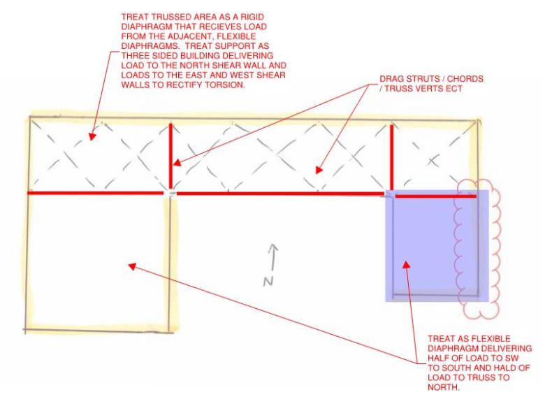
Can A Wood Sheathed Diaphragm Be Classified As A Rigid Diaphragm Woodworks
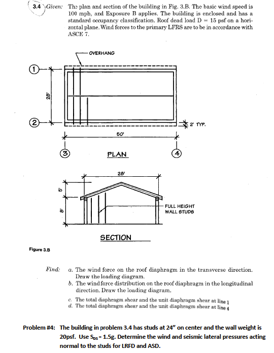
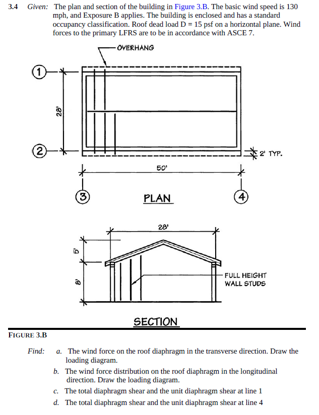
Solved 3 4 Given The Plan And Section Of The Building Chegg Com
Https Www Awc Org Pdf Education Des Awc Des431 Demystifyingdiaphragmdesign 190711 Color Pdf
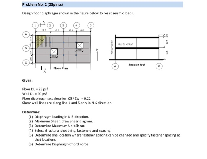
Design Wall Shown On The Figure Below To Resist Se Chegg Com

Structural Design Of Lateral Resistance To Wind And Earthquake For The Home Inspector Internachi
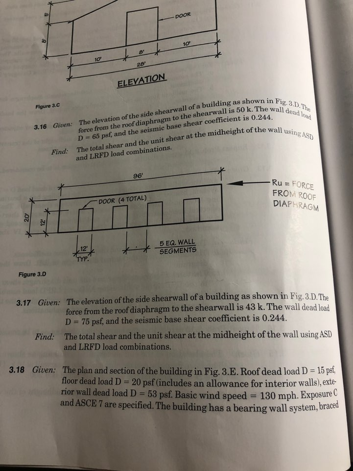
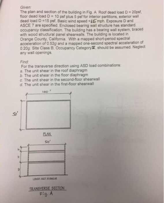
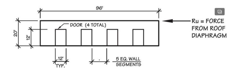
A shear wall however is a vertical cantilevered diaphragm.
Roof diaphragm unit shear.
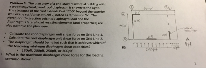
Solved Problem 3 The Plan View Of A One Story Residentia Chegg Com
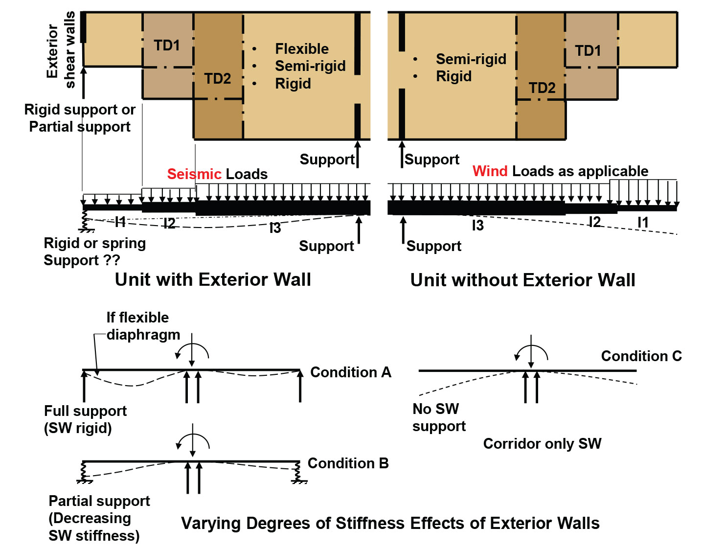
How Do You Distribute Seismic Diaphragm Force Structural Engineering General Discussion Eng Tips
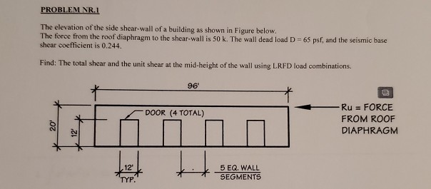
Problem Nr 1 The Elevation Of The Side Shear Wall Chegg Com
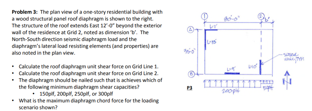
Problem 3 The Plan View Of A One Story Residentia Chegg Com
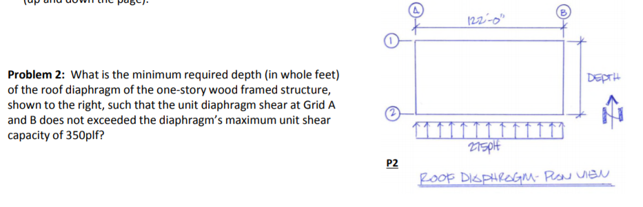
Solved A O Problem 2 What Is The Minimum Required Dept Chegg Com
Structure Magazine Design Of Reinforced Concrete Diaphragms For Wind
Pfhn Fbfymrynm
Https Www Woodworks Org Wp Content Uploads 16ws05 Chicago Wind Workshops Hour 3 Shearwalls And Diaphragms Pdf
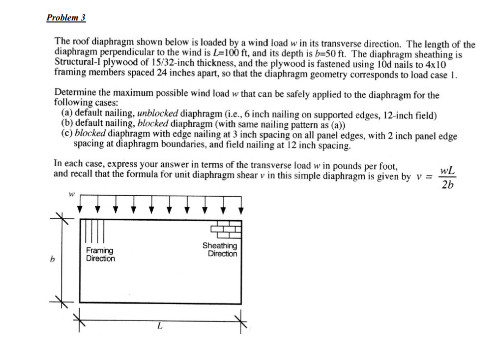
Problem 3 The Roof Diaphragm Shown Below Is Loaded Chegg Com

Horizontal Diaphragms Ppt Video Online Download
Structure Magazine Drag Trusses
The Elevation Of The Side Shear Wall Of A Building Chegg Com
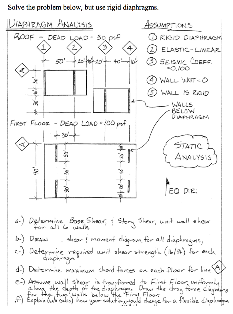
Solve The Problem Below But Use Rigid Diaphragms Chegg Com
Https Www Awc Org Pdf Education Des Awc Des413 1 Shearwallexamples 1hr 140822 Pdf
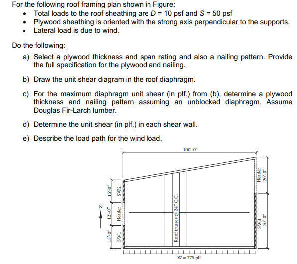
For The Following Roof Framing Plan Shown In Figur Chegg Com
Structure Magazine 5 Over 2 Podium Design
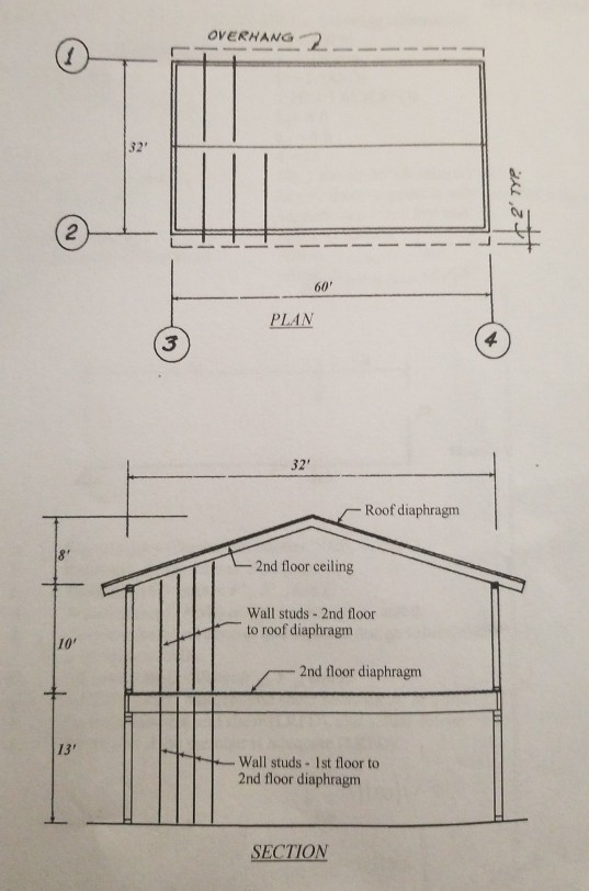
Oe2potnts Given The Plan And Section Of The Two Chegg Com
3 19 Repeat Prob 3 18 Except That Lrfd Load Combi Chegg Com
Https Encrypted Tbn0 Gstatic Com Images Q Tbn 3aand9gcrbpxrliwdewnrquce0kslscyt Mrjx7eok0wks7fl1hje59mn7 Usqp Cau
Given The Plan And Section Of The Building In Fig Chegg Com

Inelastic Response Of Steel Roof Deck Diaphragms With Nailed And Welded Connections Sciencedirect
The Elevation Of The Side Shear Wall Of A Building Chegg Com

Analysis Of Irregular Shaped Diaphragms Civil Structural Engineer Magazine

Appropriate Overstrength Of Shear Reinforcement In Precast Concrete Diaphragms Journal Of Structural Engineering Vol 133 No 11
Source : pinterest.com
